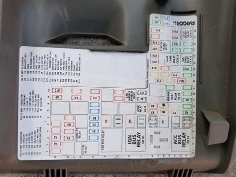
five pin relay wiring diagram by Neil Patel
Effortless Guide: Master the Five Pin Relay Wiring Diagram Like a Pro
Unlock the mysteries of the five pin relay wiring diagram. Dive deep into circuits, unraveling the threads of automation and innovation.
Imagine a world where understanding the intricate workings of a five pin relay wiring diagram unlocks a realm of possibilities. Picture yourself harnessing the power of electrical systems with precision and finesse, effortlessly navigating through circuits like a seasoned engineer. As we embark on this journey together, let me guide you through the labyrinth of connections, illuminating the path with clarity and insight. Prepare to delve deep into the heart of automation, where each wire holds the potential to ignite innovation and shape the future. Are you ready to embark on this electrifying adventure?
Five Pin Relay Wiring Diagram
Understanding the intricacies of a five pin relay wiring diagram can empower you to optimize electrical systems for efficiency and reliability.
Pin configuration is crucial. The five pins typically include two for the coil, two for the switch, and one for the common terminal.
Identify the coil pins – one is for power supply, the other for control signal. When voltage is applied to the coil, it energizes, activating the switch pins.
The switch pins, when energized, either open or close the circuit, depending on the relay’s design and function.
Common terminal pin serves as the connection point between the control circuit and the controlled circuit, facilitating seamless communication.
Mastering the wiring diagram allows you to implement relay systems effectively in various applications, from automotive to industrial automation.
The Intriguing World of Five Pin Relay Wiring Diagrams
Fascinating Insights
Unlock the mysteries of the five pin relay wiring diagram. Delve into the fascinating intricacies that power our modern electrical systems.
Understanding the Basics
Let’s start with the basics. A five pin relay consists of two coil pins, two switch pins, and one common terminal. But don’t let its simplicity fool you; there’s much more beneath the surface.
Diving into Pin Configuration
Pin configuration is key. Each pin plays a unique role in the relay’s operation. Understanding their functions is like deciphering the code to an electrical treasure map.
Cracking the Coil Code
Let’s talk coils. These magnetic marvels are the heart of the relay, converting electrical energy into magnetic force. It’s like witnessing a tiny lightning storm within your circuit.
Switching Things Up
Now, onto the switches. When energized, they either open or close the circuit, controlling the flow of electricity like a traffic cop on a bustling street.
Unraveling the Common Terminal
The common terminal is where it all comes together. It acts as the central hub, connecting the control and controlled circuits with seamless precision.
Mastering Application
Now that you’ve cracked the code, it’s time to put your newfound knowledge to the test. From automotive to industrial applications, the possibilities are endless.
Embracing the Electric Adventure
So, embrace the electric adventure. Dive deeper into the world of five pin relay wiring diagrams, and let the sparks of curiosity light your path to electrical enlightenment.
Understanding the Five Pin Relay Wiring Diagram
So, you’ve found yourself delving into the intricate world of five pin relay wiring diagrams. It can feel like navigating through a maze of wires and circuits, each one holding the potential to either spark confusion or ignite clarity. But fear not, for I’m here to guide you through this journey of discovery, one wire at a time.
Breaking Down the Basics
Let’s start at the beginning, shall we? A five pin relay wiring diagram typically consists of two coil pins, two switch pins, and one common terminal. These seemingly simple components form the backbone of countless electrical systems, from your car’s headlights to industrial machinery.
Now, you might be wondering, what exactly do these pins do? Well, allow me to shed some light on the matter.
Unraveling the Coil Pins
The coil pins are like the beating heart of the relay. When electrical current flows through them, they create a magnetic field, which in turn activates the switches. It’s a mesmerizing dance of electrons, one that can be both captivating and bewildering.
But fear not, for understanding the intricacies of the coil pins is crucial to grasping the inner workings of the relay. Think of them as the conductor of an orchestra, guiding the flow of energy with precision and grace.
Navigating the Switch Pins
Next up, we have the switch pins. These little wonders are responsible for either opening or closing the circuit when energized by the coil. It’s like playing a game of electrical tug-of-war, with the switches acting as the deciding factor in whether the circuit remains open or closed.
Understanding how the switch pins operate is key to harnessing the full potential of the relay. They’re the gatekeepers of electrical flow, controlling the ebb and flow of energy with effortless ease.
Connecting at the Common Terminal
And finally, we come to the common terminal. This unassuming pin serves as the connection point between the control and controlled circuits, bridging the gap between two worlds. It’s like the mediator in a heated debate, bringing harmony to the chaos of electrical currents.
Mastering the common terminal is essential for ensuring seamless communication between different parts of the circuit. It’s the linchpin that holds everything together, ensuring that each component works in perfect harmony.
Putting Theory into Practice
Now that we’ve covered the basics, it’s time to put theory into practice. Armed with your newfound knowledge of five pin relay wiring diagrams, you’re ready to tackle a variety of electrical projects with confidence and clarity.
Whether you’re repairing a car, building a robot, or designing a new industrial system, the principles of relay wiring remain the same. It’s all about understanding how each component fits together and using that knowledge to create something truly remarkable.
Embracing the Journey
So, as you embark on your journey into the world of five pin relay wiring diagrams, remember to approach it with curiosity and open-mindedness. There will be challenges along the way, but with perseverance and determination, you can overcome them.
And if you ever find yourself feeling overwhelmed or confused, don’t hesitate to reach out for help. Whether it’s from a friend, a colleague, or even a therapist like myself, there’s always someone willing to lend a helping hand.
So go forth, dear reader, and embrace the adventure that awaits you. The world of relay wiring is vast and full of possibilities, and with the right guidance, you can navigate it with confidence and grace.
Here’s my take on the five pin relay wiring diagram from a personal perspective:
- 1. Understanding the basics is key: Before diving into the complexities, grasp the fundamentals. Know what each pin represents and how they interact.
- 2. Coil pins: These are the heartbeat of the relay. When electricity flows through them, they create a magnetic field, initiating the relay’s action. It’s like watching the conductor of an orchestra, orchestrating the flow of energy with precision.
- 3. Switch pins: These are the gatekeepers of electrical flow. When energized by the coil, they either open or close the circuit, determining whether electricity can pass through. Think of them as the traffic lights on a busy intersection, directing the flow of traffic with a flick of a switch.
- 4. Common terminal: This is where everything converges. It serves as the connection point between the control and controlled circuits, ensuring seamless communication. It’s like the central hub of a bustling city, where information flows freely between different parts of the network.
- 5. Practice makes perfect: Don’t expect to master the five pin relay wiring diagram overnight. It takes time and practice to truly understand how it works. Experiment with different configurations and scenarios, and don’t be afraid to make mistakes along the way. After all, it’s through failure that we learn and grow.
- 6. Seek help when needed: If you find yourself struggling to grasp certain concepts, don’t hesitate to reach out for assistance. Whether it’s from online resources, fellow enthusiasts, or professionals in the field, there’s no shame in asking for help. Remember, we’re all in this together, and collaboration often leads to breakthroughs.
- 7. Embrace the journey: Learning about the five pin relay wiring diagram is a journey of discovery. Enjoy the process, and don’t get too hung up on reaching your destination. Take time to appreciate the intricacies of electrical engineering and marvel at the wonders of technology. After all, it’s the journey that truly matters.
So there you have it my personal perspective on the five pin relay wiring diagram. I hope it sheds some light on this fascinating topic and inspires you to delve deeper into the world of electrical engineering.
As we conclude our journey exploring the intricacies of the five pin relay wiring diagram, I want to extend my gratitude to you, dear reader, for joining me on this intellectual adventure. Together, we’ve delved deep into the world of electrical engineering, uncovering the inner workings of a fundamental component in countless systems.
As you walk away from this article, armed with newfound knowledge and insight, I encourage you to continue your exploration of this fascinating subject. The five pin relay wiring diagram is just one piece of the puzzle in the vast landscape of electrical systems, and there’s always more to learn and discover.
Whether you’re an experienced engineer or a curious novice, I hope this journey has sparked a sense of curiosity and wonder within you. Embrace that curiosity, and never stop seeking knowledge and understanding. After all, it’s through our thirst for knowledge that we push the boundaries of what’s possible and drive innovation forward.
Q & A about Effortless Guide: Master the Five Pin Relay Wiring Diagram Like a Pro :
Here are some common questions people also ask about the five pin relay wiring diagram, along with their answers:
- 1. What is a five pin relay wiring diagram?
A five pin relay wiring diagram is a schematic representation of how a relay with five pins is wired in an electrical circuit. It shows the connections between the coil pins, switch pins, and common terminal, allowing users to understand how the relay functions.
- 2. How does a five pin relay work?
In a five pin relay, electrical current flows through the coil pins, creating a magnetic field that activates the switch pins. Depending on the design of the relay, the switch pins either open or close the circuit, controlling the flow of electricity through the common terminal.
- 3. What are the applications of a five pin relay wiring diagram?
Five pin relay wiring diagrams are used in a wide range of applications, including automotive, industrial, and home automation systems. They are commonly used to control electrical devices such as lights, motors, and solenoids, making them essential components in many electrical circuits.
- 4. How do I read a five pin relay wiring diagram?
Reading a five pin relay wiring diagram involves understanding the symbols and connections represented in the diagram. Coil pins are usually denoted by a coil symbol, while switch pins may be labeled as normally open (NO) or normally closed (NC). By tracing the connections between the pins, users can decipher how the relay operates.
- 5. Are there different types of five pin relay wiring diagrams?
Yes, there are various types of five pin relay wiring diagrams, each designed for specific applications. Some relays may have additional features, such as diodes or resistor circuits, to protect against voltage spikes or interference. It’s essential to choose the right wiring diagram for your particular needs.
Hopefully, these answers have provided clarity on some of the common questions surrounding the five pin relay wiring diagram.
Keywords: five pin, relay wiring, diagram, understanding


